Friday, March 25, 2011

So you still have issues opening many shared Exchange 2010 calendars using Outlook 2003?

Even though you tried all the steps in the “Opening multiple shared calendars & additional mailboxes” section of the “Concern: Is having Outlook 2003 clients going to prevent me from deploying Exchange 2010?” TechNet Wiki article, I wrote some months ago.

So during a recent Exchange 2003 > Exchange 2010 transition at a customer that only had Outlook 2003 clients and relied heavily on shared calendars, I discovered an additional issue. Even though I had configured the value of the “RCAMaxConcurrency” setting in the default throttling policy to unlimited ($null), some users still saw the dreaded “The action could not be completed. The connection to the Microsoft Exchange Server is unavailable. Outlook must be online or connected to complete this action. error message. In addition, event 9646 with a description similar to the following was logged in the application log on the Mailbox servers in the organization:

“Mapi session “00cc8dde-64d7-4353-8050-00fc2057aae3: /O=xxxx/OU=xxxx/cn=Recipients/cn=John” exceeded the maximum of 32 objects of type “session”.”
 
So after some researching and communication with two Exchange Escalation Engineer buddies (Steve Swift and Will Duff) from the Exchange Enterprise Support team in Charlotte, I finally nailed the issue. The issue wasn’t really related to the Exchange RPC CA service, but a limit set on the Exchange Information Store. Yes same limit as you probably have seen in previous Exchange versions.

To fix it, you need to increase the limit for MAPI sessions using an Exchange Information Store registry key. The keys to use are covered here: http://technet.microsoft.com/en-us/library/ff477612.aspx, but when I tried to add the “szMaxAllowedSessionsPerUser and/or “szMaxAllowedServiceSessionsPerUser”, I still saw 9646 in the app log.

Guess why? yes the registry keys are actually listed with wrong names in that article. Instead of:
  • szMaxAllowedSessionsPerUser  
  • szMaxAllowedServiceSessionsPerUser
You need to use:
  • Maximum Allowed Sessions Per User
  • Maximum Allowed Service Sessions Per User
And then everything worked as expected…
Hopefully the TechNet page is updated soon.

VMware, NetApp De-Dup, and Effects on Exchange 2010 DAG

The first time I read about Database Availability Groups (DAG) in Exchange 2010 I instantly thought of what a great fit NetApp de-duplication would be for storing database copies.  NetApp claims 10-30% de-duplication on Exchange 2010 databases, but they do not mention space savings of identical copies of databases.  Technically this number should be close to 100% space savings (after a de-dup job completes) so long as your database copies live in the same volume.


As far as I know NetApp is currently the only storage vendor that actually recommends running production data de-duplication so these comparisons will also encompass what I call NNS (Non NetApp Storage).  I also make the assumption that when running JBOD you will be using lag database copies.  Since we can (and will) take snapshots on the array and have no need for lag copies I have factored in an additional 20% storage for snap space on the NetApp.  Additionally I have set the single database de-dup number at 15% for all the calculations in this article.


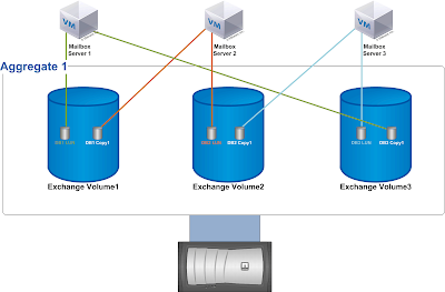
Take the example below where we place all the database copies on the same volume, but present the LUN's to the different servers in the DAG.  The downside to this scenario is if you lose a volume or aggregate you will have lost all the protection capabilities afforded you by the database copies in the first place.  Personally I have never experienced the loss of an entire aggregate or volume, and I believe the event to be highly unlikely.  This particular scenario all boils down to your own comfort level with your back-end storage array.  It should be noted if you stretch your DAG across physical locations then you have successfully mitigated this risk.  You can expect to see about a 73% space reduction over JBOD or NNS.

Scenario 1

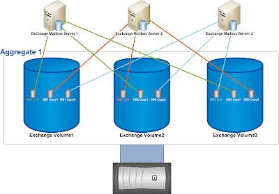
If you do not have a DR site (bad idea) you can provide protection from an aggregate failure by putting your database on separate physical spindles.  This example outlines the process.  You do not game the same level of data de-duplication that you do in the first scenario, but you do gain better protection.  You can expect to see about a 58% space reduction over JBOD or NNS.

Scenario 2

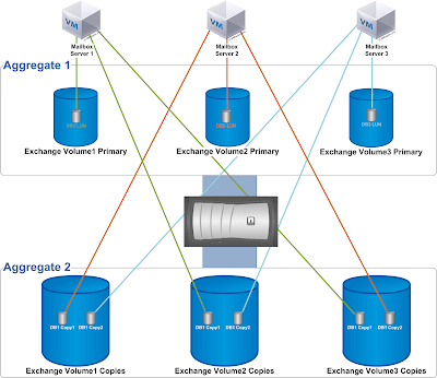
Here is a similar scenario as the first, only this time we use VMware virtual machines configured in a HA cluster instead of physical servers.  This lets us reduce our database copies by 1 per database since we no longer need 3 copies.  Microsoft recommends 3 copies so you are protected against hardware failure in the event you have a database offline for maintenance, but we gain that protection in the form of VMware HA.  You could still add an additional database copy if you wish, and it would take up the same amount of space as having 1 copy.  Space savings is the same as scenario 1 at about 73%.
Scenario 3

My favorite scenario is listed below.  This design is easy to manage, and is a good balance between data protection and space savings.  We use the same design as the diagram above, but here we use VMware SRM to replicate our virtual machines and SnapManager for Exchange and SnapMirror to replicate the databases to a DR site.  This is the same space savings as scenario 2, but you will reclaim Microsoft licensing cost by leveraging SRM.


Scenario 4

Microsoft has done an outstanding job with Exchange 2010 giving customers all the options they need to deploy a highly reliable and redundant messaging solution.  Leveraging VMware and NetApp storage you have even more options, and gain even greater functionality.  NetApp TR-3824, "Storage Efficiency and Best Practices for Microsoft Exchange Server 2010" does not recommend placing database copies in the same volume, but based on what I have presented here I'll leave it for you to decide the risk/reward.

Thursday, March 24, 2011

Information Store timeout detection in Exchange 2007 SP3

Exchange Server 2007 Service Pack 3 introduces a new feature that monitors the Information Store service for long running transactions. Transactions are now timed and if a transaction lasts longer than 60 seconds (hardcoded), it's considered to be timed out. The transaction isn’t terminated; it’s just flagged as taking too long.

This monitoring has been added to help report on the health of the Information Store. There is a myriad of reasons for long running transactions. Some of these reasons are explained in Understanding the Performance Impact of High Item Counts and Restricted Views.

Update: Timeout detection and reporting was introduced in Exchange 2010 RTM and backported to Exchange 2007 SP3. See Understanding the Exchange 2010 Store -> Time-Out Detection and Reporting.

In isolation, an individual long running transaction may or may not be of concern. If the transaction doesn’t involve any locking, it will proceed in isolation without harm (assuming CPU and Memory are scaled appropriately). If it does use locking however, it can be quite harmful to the experience of other clients as they wait for the locked resource to be released.

If the prevalence of long transactions increases over time, the monitoring more than likely indicates that there are various problems (data corruption, high item counts, disk performance, memory pressure, CPU pressure).

The new timeout detection logs entries in the Application event log at the following three levels of severity:
  • Server Level
  • Database Level
  • Mailbox Level
Each level is associated with a scope and threshold: Server – any 20 threads; Database – 10 threads per database; Mailbox – 5 threads per mailbox. The following entries are logged in the event log for each level:
[Server Level – 20+ threads]
MessageID=10025
Source=MSExchangeIS
Severity=Error
Facility=General (6)
Language=English
There are %1 RPC requests that take abnormally long time to complete. It may be indicative of performance problems with your server.

·         [Database Level – 10+ threads per database]
MessageID=10026
Source=MSExchangeIS
Severity=Error
Facility=General (6)
Language=English
There are %1 RPC requests for the database "%2" that take abnormally long time to complete. It may be indicative of performance problems with your server.

·         [Mailbox Level – 5+ threads per mailbox]
MessageID=10027
Source=MSExchangeIS
Severity=Error
Facility=General (6)
Language=English
There are %1 RPC requests for the mailbox "%2" on the database "%3" that take abnormally long time to complete. It may be indicative of performance problems with your server.

When an Event Log entry is logged, the MSExchangeIS\RPC Request Timeout Detected performance counter is incremented:

This feature can be disabled by setting this registry value to 1. The default is enabled (0 or not set).

Path: HKLM\SYSTEM\CurrentControlSet\Services\MSExchangeIS\ParametersSystem
Name: DisableTimeoutDetection
Type: DWORD
Value: 1

Outlook 2010 Where did Message Headers go !!!

If you noticed message headers in outlook 2010 is not where you would see them on outlook 2007 , simple right click and going message options seems to be missing from outlook 2010. Time to time you might need that option or even ask your client to get there if you need the header information. Recent post on MSexchange team is showing how to bring the valuable future back into outlook 2010.
  • Open Outlook , Click on down arrow in the Quick Access Toolbar
image
Pick all commands
image
message options click add.
image
now you see it on top
image

Tuesday, March 22, 2011

Designing a Highly Available Database Copy Layout

Exchange 2010 introduced the database availability group (DAG), which enables you to design a mailbox resiliency configuration that is essentially a redundant array of independent Mailbox servers. Multiple copies of each mailbox database are distributed across these servers to enable mailboxes to remain available during one or more server or database outages.

As part of your design process, you need to design a balanced database copy layout, which may in turn, require you to revisit several design decisions to derive the optimal design. The following design principles should be used when planning the database copy layout:

Design Principle 1: Ensure that you minimize multiple database copy failures of a given mailbox database by isolating each copy from one another and placing them in different failure domains. A failure domain is a component or set of components that comprise a portion of the overall solution architecture (e.g., a server rack, a storage array, a router, etc.). For example, you would not want to place more than one database of a given mailbox database within the same server rack, or host it on the same storage array. If you lose the rack or the array, you end up losing multiple copies of the same database (perhaps your only copies!).

Design Principle 2: Distribute the database copies across the DAG members in a consistent and efficient fashion to ensure that the active mailbox databases are evenly distributed after a failure. The sum of the Activation Preference values of each database copy on each DAG member should be equal or close to equal, as this configuration will result in an approximately equal distribution of active copies throughout the DAG after a failure (assuming replication is healthy and up-to-date).

In order to follow these design principles, we recommend you place the database copies in a particular arrangement to ensure that the active copies are symmetrically distributed across as many servers as possible. This arrangement of database copies is based on a “building block” concept.

1. The first building block (known as the Level 1 Building Block) is based on the number of mailbox servers that will host active database copies. Assume this number is N. N defines not only the number of Mailbox servers, but also the number of databases within the building block. One active database copy is distributed on each server forming a diagonal pattern represented on the diagram below.

For example, let’s say we have 4 servers, each with its own dedicated storage and deployed in a separate server rack, and we want to deploy 24 databases with 3 copies of each database. In this case, the size of our first level 1 building block is 4 and looks like this (copy layout is highlighted in yellow):

Image

The same pattern is then repeated for each remaining level 1 building block set (given 24 databases, there are six Level 1 Building Block sets in this example).

Image

2. As you add second database copies, you place them differently for each building block set. Since one server is already hosting the active copy, there are N-1 servers available to host the second database copy. As you use each of these N-1 servers once, you have a complete symmetric distribution which will form the new larger building block. Therefore the new building block (known as the Level 2 Building Block) size becomes N*(N-1) databases. This means that the second database copy for the first database is placed on the second server, and each second copy thereafter is deployed in a diagonal pattern within the building block. After the pattern is completed within the first Level 1 Building Block set, the starting position of the second copy for the next block is offset by one so that the second copy starts on the third server.

In our example, the building block size now becomes 4*(4-1) = 4*3 = 12, which means that 12 databases make up each Level 2 Building Block set. Note that for the Level 1 Building Block set 1 (DB1-DB4), the second copy for DB1 is placed on Server 2, while for the Level 1 Building Block set 2 (DB5-DB8), the second copy for DB5 is placed on Server 3. Each Level 1 Building Block set starting server for placement is offset from the previous one by one server. This layout is continued by placing the second copy for DB9 on server 4. This ensures that a server 1 failure will activate second copies across all three remaining servers rather than activating multiple databases on the same server, which provides a balanced activation.

Image

This pattern is then repeated for each remaining Level 2 Building Block set (given 24 databases, there are two Level 2 Building Block sets in this example). Note that the second copy for DB13 is placed on Server 2.

Image

To understand this logic better, compare database copy placement for databases 1, 5, and 9. All of these databases have the active copy hosted on server 1, so if this server fails, you want to have second database copies activated on different remaining servers to achieve equal load distribution. This is what you achieve by placing second database copy of DB1 on server 2, second database copy of DB5 on server 3, and second database copy of DB9 on server 4. Starting with DB13, you simply repeat the pattern.

The rest of the database copies are added in a diagonal pattern (bolded):

Image

3. As you add a third database copy, again you need to place it differently for each group of now N*(N-1) databases. Since now you have only N-2 servers available to choose from for the third database copy placement, this generates N-2 variations, such that the new building block (known as the Level 3 Building Block) becomes N*(N-1)*(N-2) databases. Therefore, the third database copy for the first database is placed on the third server, and each third copy thereafter is deployed in a diagonal pattern according to that starting position within this new building block. After the pattern is completed within the first Level 1 Building Block set, the starting position is offset by one so that the third copy is placed in the fourth position.

In this example, our building block now becomes 4*(4-1)*(4-2) = 4*3*2 = 24, which means that 24 databases make up each Level 3 Building Block set. To produce the symmetric database placement pattern, place the third database copy of DB1 on Server 3 (this is the first available server because Server 1 hosts the first copy and Server 2 hosts the second copy), and offset each next copy by 1 until you reach the end of the Level 1 Building Block set 1. For the next building block set, again place the third database copy on the next available server (Server 4), and continue in the same manner until you reach DB12 which marks the end of the Level 2 Building Block set 1. For databases 13-20, follow the same pattern but offset third database copy placement by 1 so that it doesn’t end up on the same servers as for databases 1-12.

Image

Again, to understand this logic better, compare database copy placement for databases 1 and 13. These databases have the active database copy hosted on server 1, and the second database copy hosted on server 2. If both servers fail, you want to have the third database copies activated on different remaining servers to achieve equal load distribution. This is what you achieve by placing the third database copy of DB1 on server 3, and the third database copy of DB13 on server 4. Similar “pairs” are formed by databases 2 and 14, 3 and 15, and so on. Starting with DB25, you would simply repeat the pattern, but this example does not have that many databases.

Image

4. As you add a fourth database copy, again you need to place it differently for each group of now N*(N-1)*(N-2) databases, such that the new building block becomes N*(N-1)*(N-2)*(N-3) databases. This follows the same logical approach and ensures that the database distribution will be even within the new building block in case of 3 server failures.

The example of 4 servers leaves only 1 variation for placing the 4th database copy (as there is only one remaining server available), so the building block size actually remains to be 24. This is also seen from the formula for building block size, as 4*3*2*(4-3) = 4*3*2*1 = 24.

5. As you continue adding more database copies, the building block keeps growing such that the general formula for the building block size is Perm(N,M) = N(N-1)…(N-M+1) = N!/(N-M)! = CNMM! (where N=number of servers and M=number of database copies). This becomes obvious as you realize that complete symmetric distribution of the database copies is achieved by selecting all possible permutations of M database copies across N available servers.

In the event of a single server failure (server 4, for example), the active mailbox databases will be distributed as follows (the second copy is activated for databases 4, 8, 12, 16, and 20, denoted in dark orange), which results in no more than 8 activated mailbox databases per server (assuming replication is healthy and up-to-date).

Image

In the event of a double server failure (the third copy is activated for several databases and denoted in green), the remaining two servers, Server 2 and Server 3, will have an equal number of activated mailbox databases (assuming replication is healthy and up-to-date).

Image

Conclusion

Hopefully this guidance helps you with planning your database copy layout. If you have any questions, please let us know.
Windows Server 2008 SMTP Service logging

I was working on installing Windows Server 2008 x64 edition. I discovered the SMTP Service wasn't logging. SMTP was working and emails were going out. My install is 'custom' and installs just the modules we needed. Turns out, there is a small dependency on the ODBC logging module so the SMTP service logging would work. More importantly iislog.dll. Here are the instructions to fix and reproduce the behavior.

To correct it. I'm assuming you have the SMTP Service already installed and it's not logging.

1) Install ODBC Logging module (role service in Server Manager)

2) Stop / Start the SMTP Service

3) Verify your SMTP service is configured for logging. It's not on by default.

4) Try a local telnet test (assuming the telnet client is installed)

5) Look at your log folder.

To Reproduce the logging 'behavior'

1) Install Windows Server 2008 (obvious step)

2) Install the basic web server components. (static content with anonymous user)

3) Install telnet client and SMTP services

4) Enable logging on SMTP instance

5) try a telnet test locally

6) Verify the smtpsvc folder isn't in the location you configured for logging (default is c:\windows\system32\logfiles)

7) Add the ODBC logging module (no iisreset is required) *Or in my tests there wasn't

8) Stop / Start the SMTP service (net stop smtpsvc && net start smtpsvc)

9) Try another telnet test

10) Verify the SMTPSVC folder is present.

Hope this saves you some time, it took me a while to find the right mix.

Thanks a bunch to Bernard Cheah who helped point me in the right direction

------------------------------------------------------------------------------------

While configuring SMTP server, I got the errors while clicking on Current Sessions. That error is “No Such Interface supported.”

Looking at that in detail and some blogs, I found that there are 2 problems:

1) Log is not created in SMTP log folder
2) We could not view current session as we got the error message “No Such Interface supported.”

Both problem is resolved by taking following steps:

1) Go to Server Manager and Install ODBC Logging module (You can search on net how to install Role Services Feature)

2) Stop and Start SMTP Server service. Enable logging in SMTP server.

3) connect SMTP server by telnet

4) Now, see if log is created in the respected log folder. If not, you can try the command to flush the log buffer

netsh http flush logbuffer
5) See if now log is created. It must be there. Else god will help you .

Now for another part, you need to register the following dll.

C:\Windows\System32\inetsrv>regsvr32 smtpsnap.dll
C:\Windows\System32\inetsrv>regsvr32 smtpadm.dll

Stop and Start SMTP Service.